Zapier Meets a Rasperry Pi: Build an Illuminated LED Logo
I love the winter in Minnesota. The long, cold, dark nights are a great time to curl up with a warm laptop and work on an "outrageously geeky" project. I also love LEDs, and connecting them with microprocessors/computers. Combining the three would make a great project.
For many months, I've thought about constructing some kind of Illuminated Zapier logo and controlling it via a Zap. During 2016's Black Friday weekend, Adafruit had a big sale on everything and I couldn't resist the opportunity to put something together.
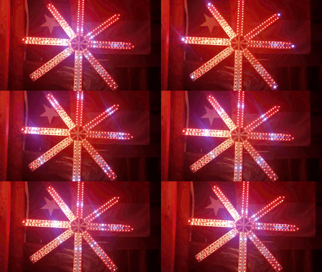
Before I could purchase the parts, I needed a plan. That involved answering the following questions:
- How large should it be (physical dimensions)?
- What kind of microprocessor should it use (Arduino, Raspberry Pi, or something else)?
- What kind of LEDs would work best (individual LEDs, or some type of LED strips)?
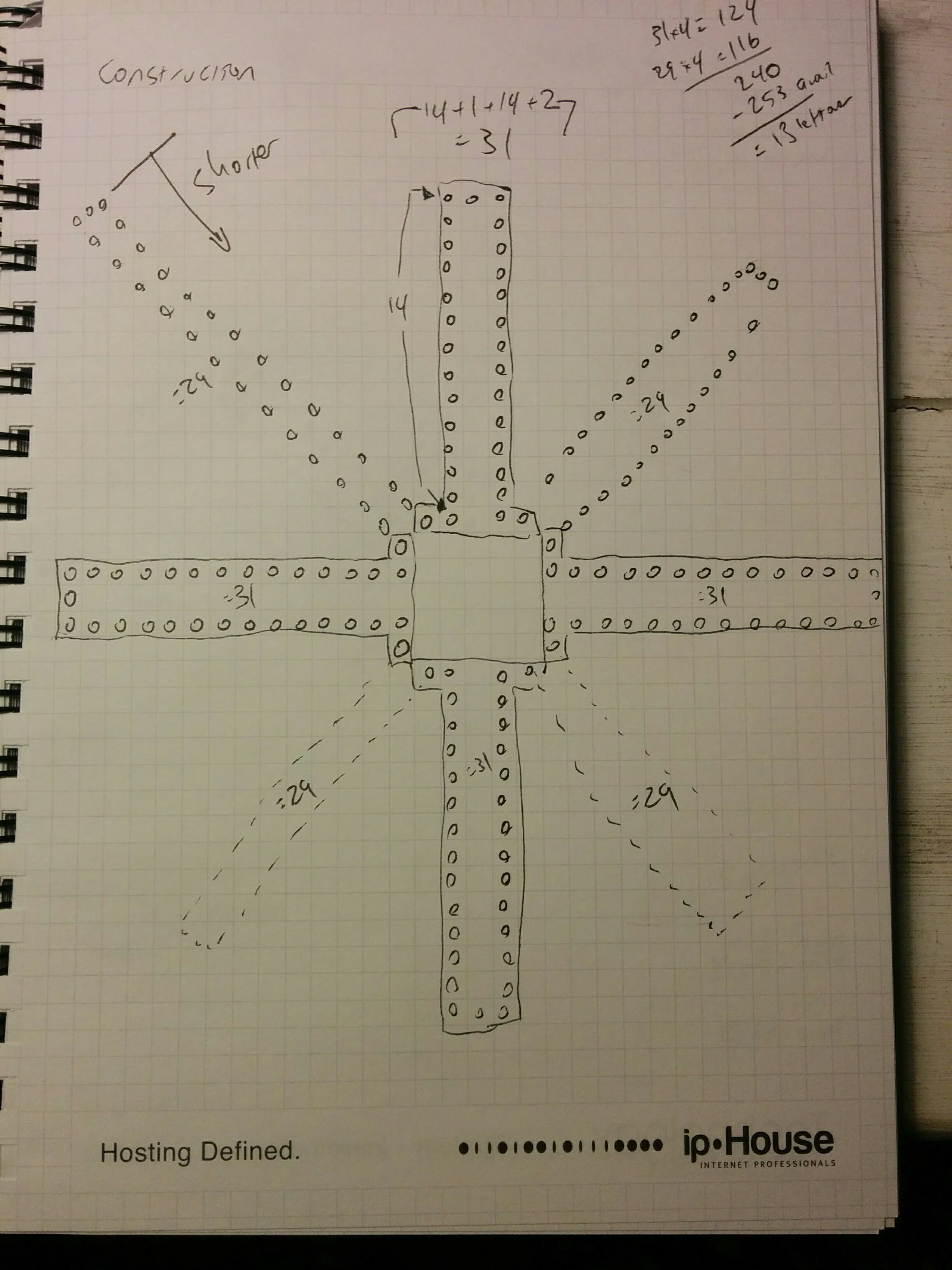
I grabbed a notepad and sketched out possible arrangements of LEDs and quantities needed to would resemble the Zapier logo:
As for the microprocessor, I wanted to control the display via the Internet so I needed some kind of Ethernet or WiFi capabilities, along with a programming language and environment that would handle communications automatically. I also needed something with General Purpose Input/Output (GPIO) pins to control the LEDs (which generally need a 5 volt signal, as opposed to 3.3 volts for communications).
Arduino vs Raspberry Pi: Pros and Cons
| Arduino | Raspberry Pi | |
|---|---|---|
| Pro |
|
|
| Con |
|
|
The biggest detraction for the Arduino was the difficulty of adding an Internet connection. I've worked on previous Arduino-based projects that required similar connectivity, and had to work around issues with the available software libraries (like manually configuring IP addresses and downloading/decoding SSL certificates in order to establish an HTTPS connection). This had me leaning towards the RasPi.
The final "big decision" was the type of LED strip to use. There are two main options:
The big difference is that the Neopixel requires a constant communication speed (for real-time control), whereas the Dotstar can handle a fluctuating data rate (useful when the bits are coming from a Javascript virtual machine).
In the end, I went with the Dotstar LED strips, and the Raspberry Pi, especially since there's a Dotstar Node/npm library that worked very well.
Prototyping
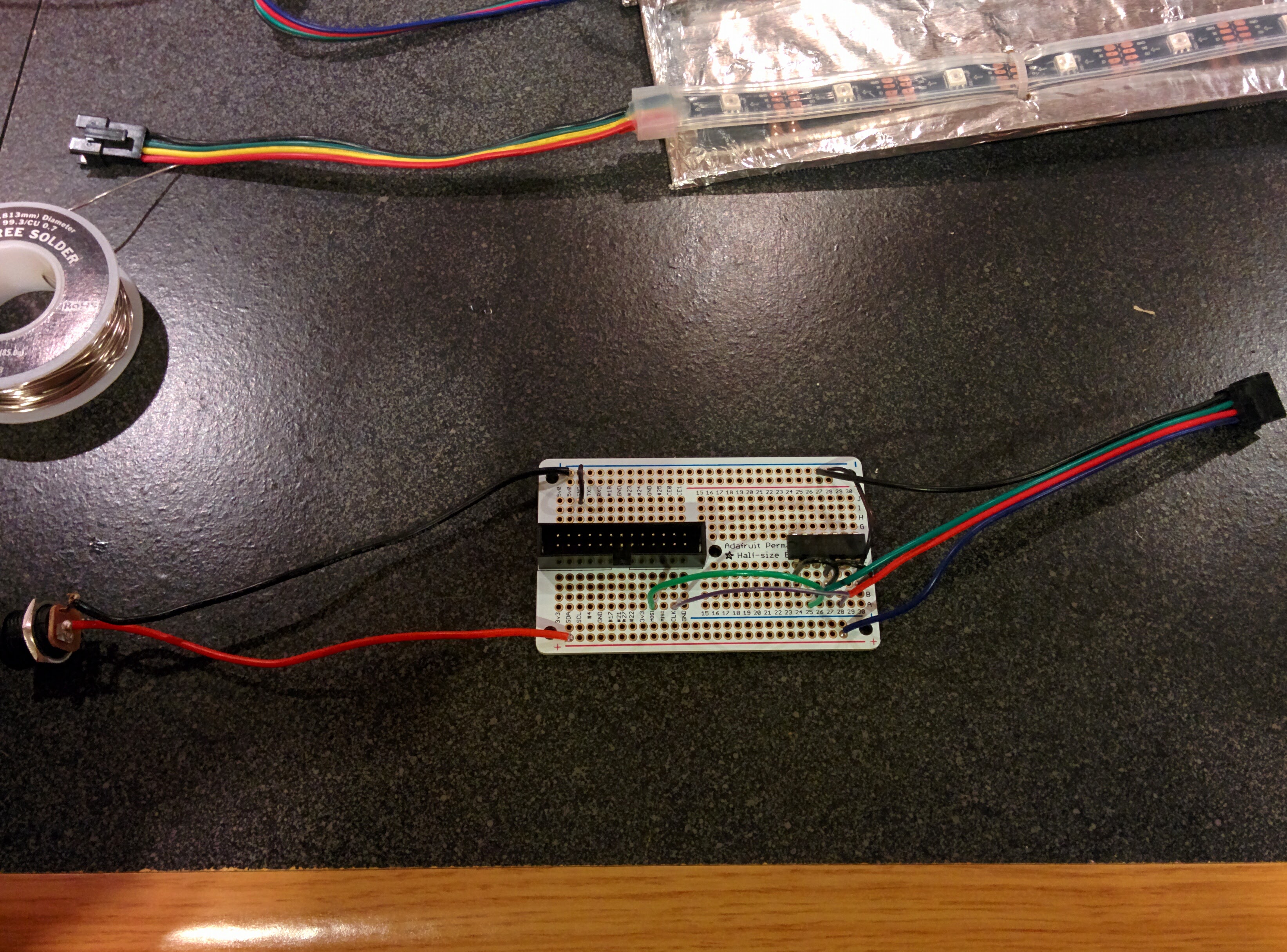
When I finally got all the parts together, I got things hooked using a small breadboard. The biggest hurdle was getting the 3.3v GPIO pins on the RasPi working with the 5v requirements of the Dotstar LEDs. Fortunately, Adafruit has a super helpful guide using a 74AHCT125 level shifting chip to safely connect 3V and 5V devices, and that approach worked great.
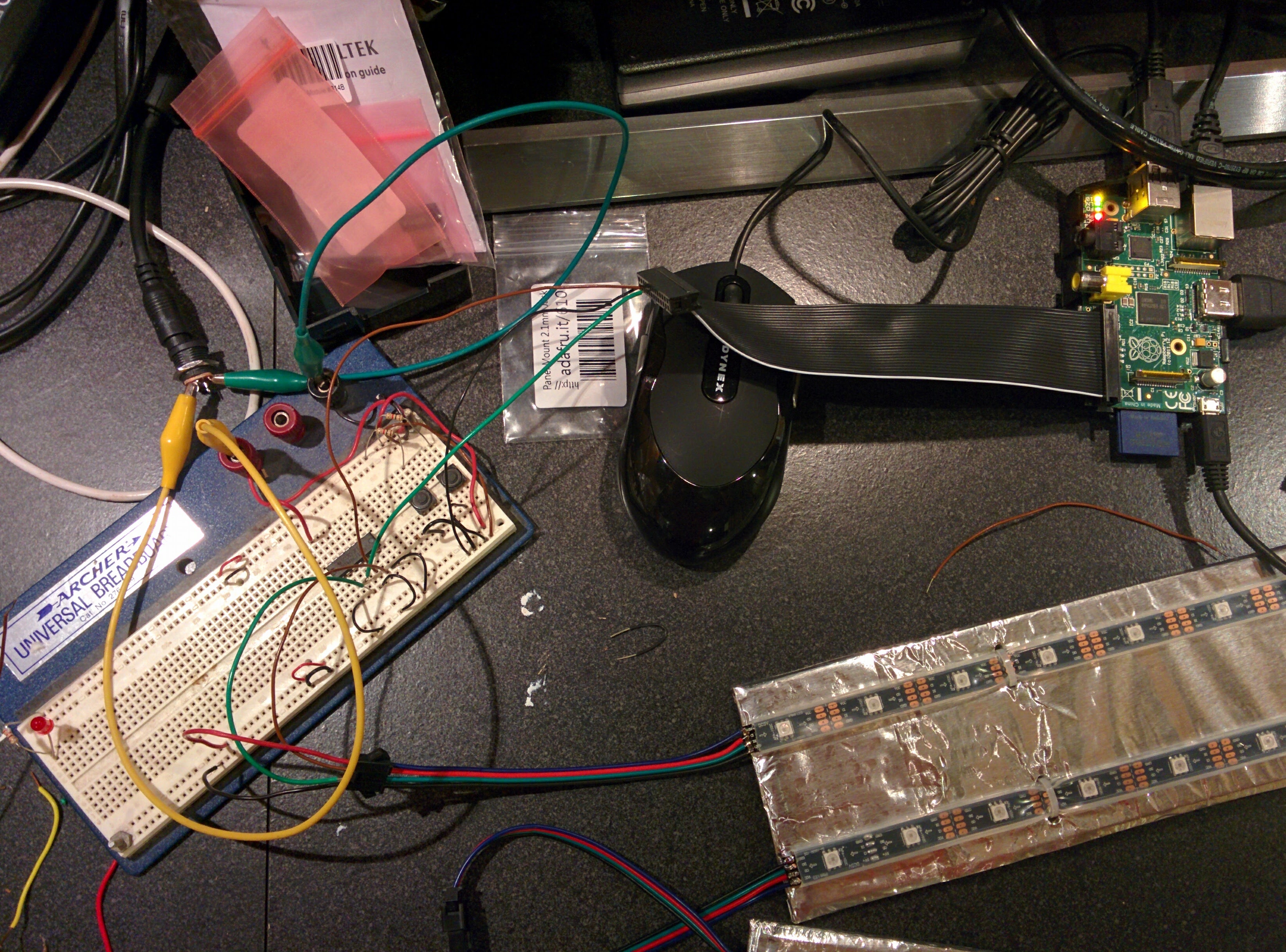
After getting things wired up, I ran a simple Node program to turn on all the LEDs, and was amazed that it all "just worked". Now that I had communications established between the RasPi and LEDs, it was time to start assembling and coding.
Assembly
The next step was figuring out the physical dimensions of the project. After working through a bunch of combinations, I decided on having each panel include 15 LEDs on each side, and then a single LED on the end—thus, 31 LEDs per panel.
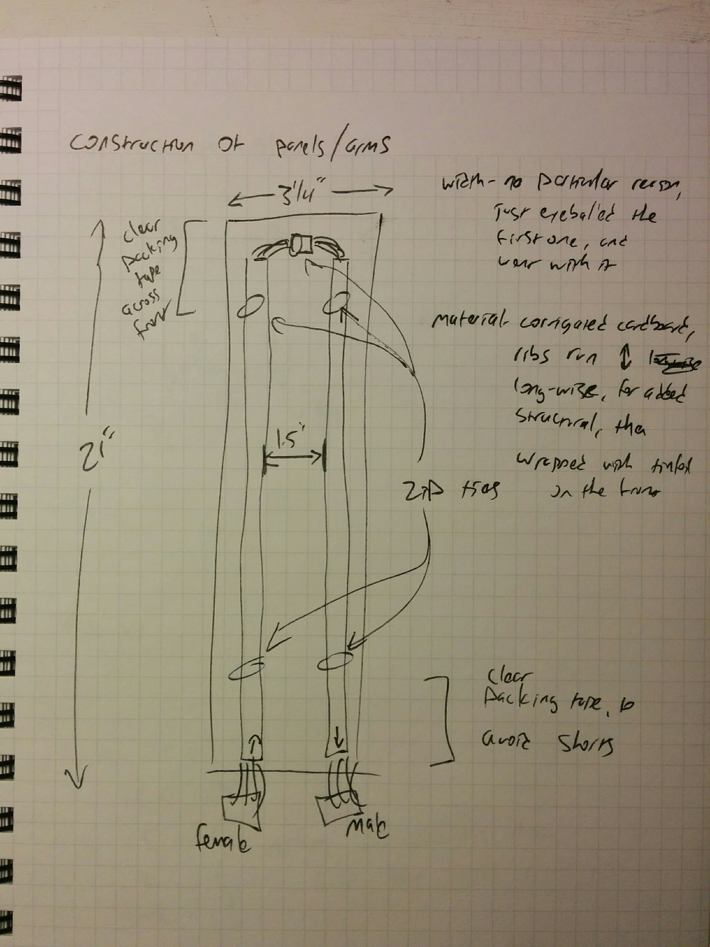
The first panel took the longest amount of time to build, as I worked out all of the steps that were needed to prepare the materials and then put everything together. After a very long night of work, I managed to finish the very first panel.
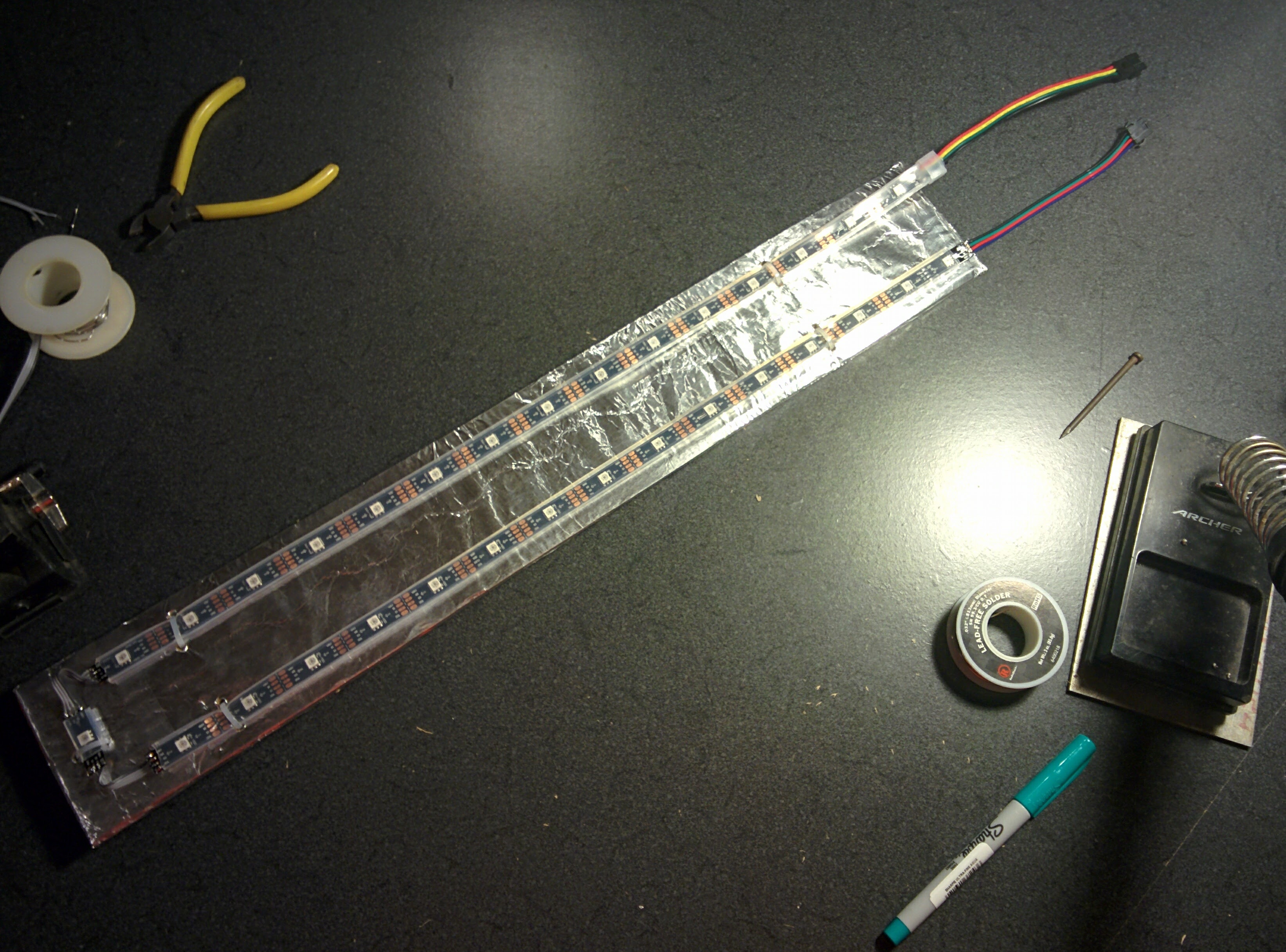
Each of the Dotstar LED strips are composed of smaller strips with 15 LEDs each, so it made for a convenient place to cut things apart.
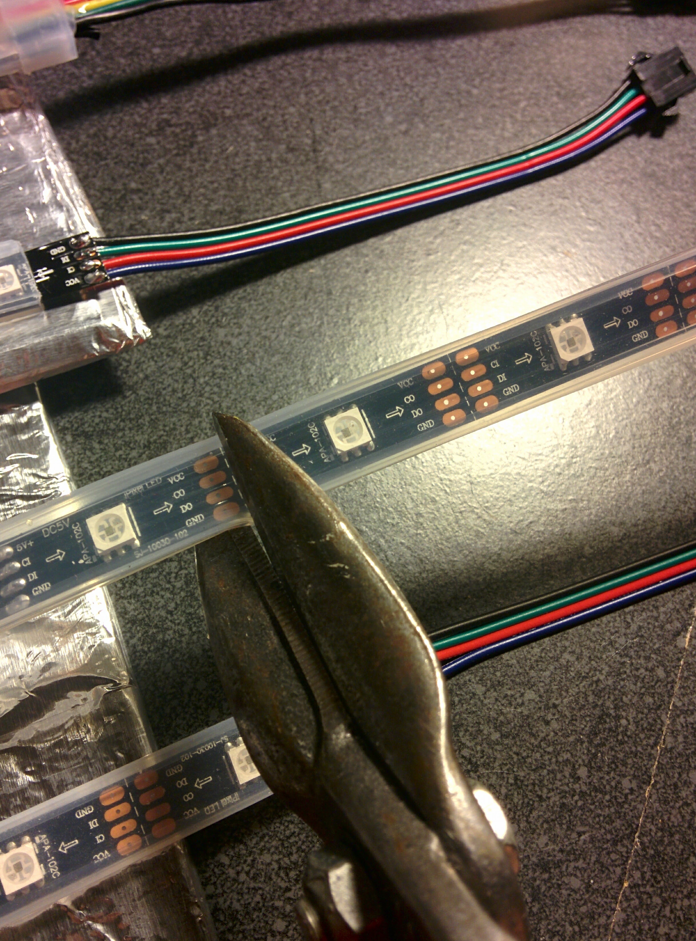
On the tip of each panel, I wanted a single LED as a finishing touch—which added a large amount of soldering and manual labor. One challenge was that the solder-holes on the LEDs were a bit too small for the wire (old ribbon cable) that I was using, so I had to use a nail to make the solder holes just a bit larger…
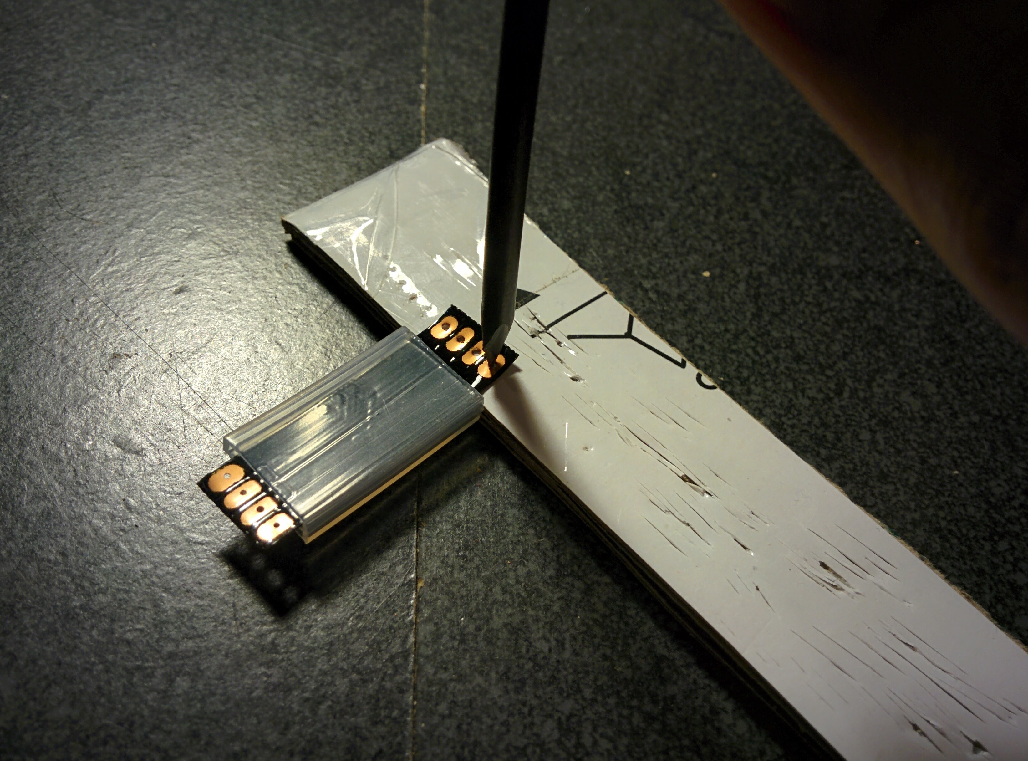
…and then solder two sections of wiring on both sides of the end-LED (thus, 16 solder connections per LED/panel, and 128 solder pads altogether).
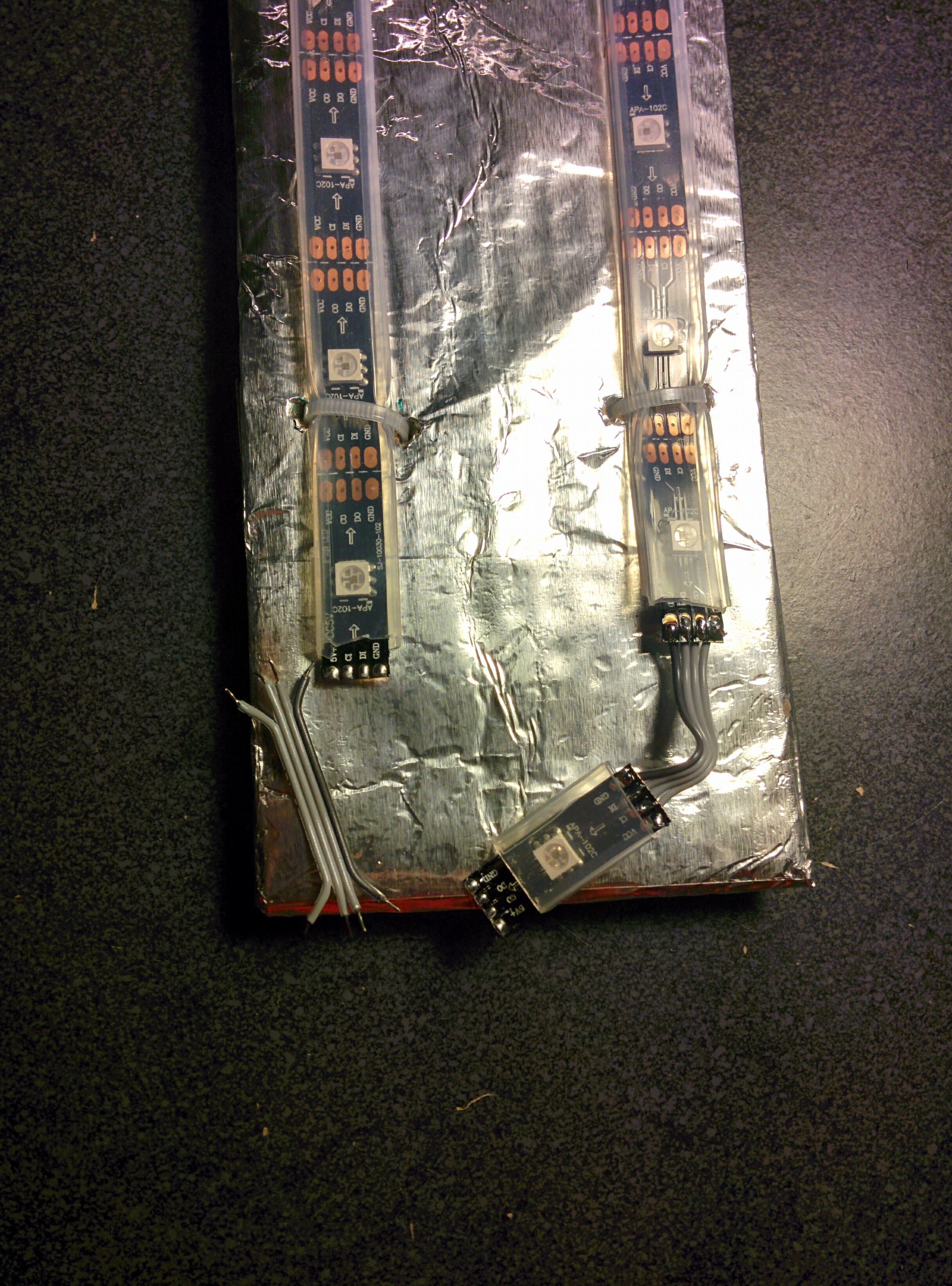
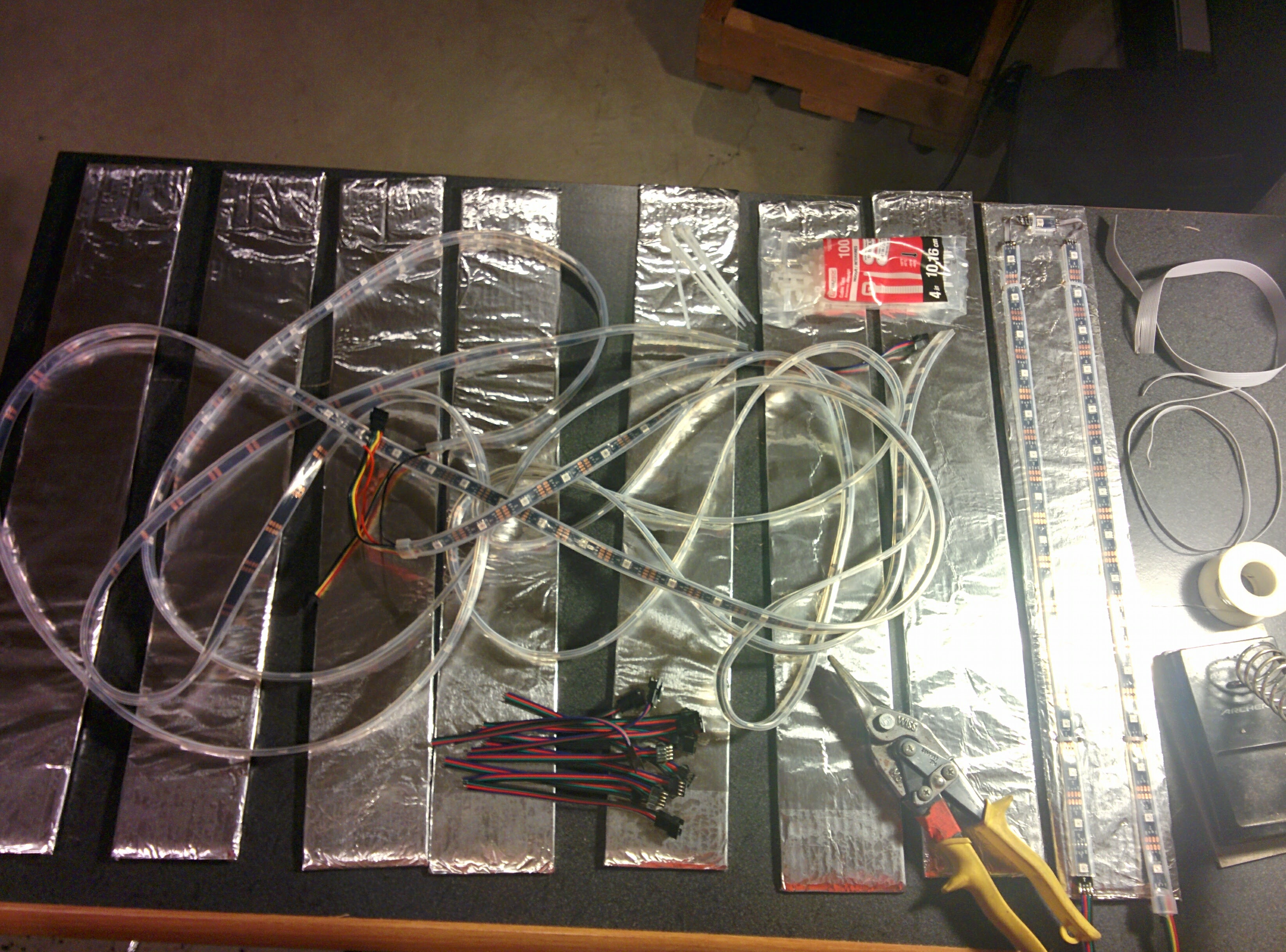
The LED strips are attached using zip-ties to old cardboard (which I wrapped in aluminum foil), and then the cardboard is attached with more zip-ties to a frame made with a bunch of PVC pipes.
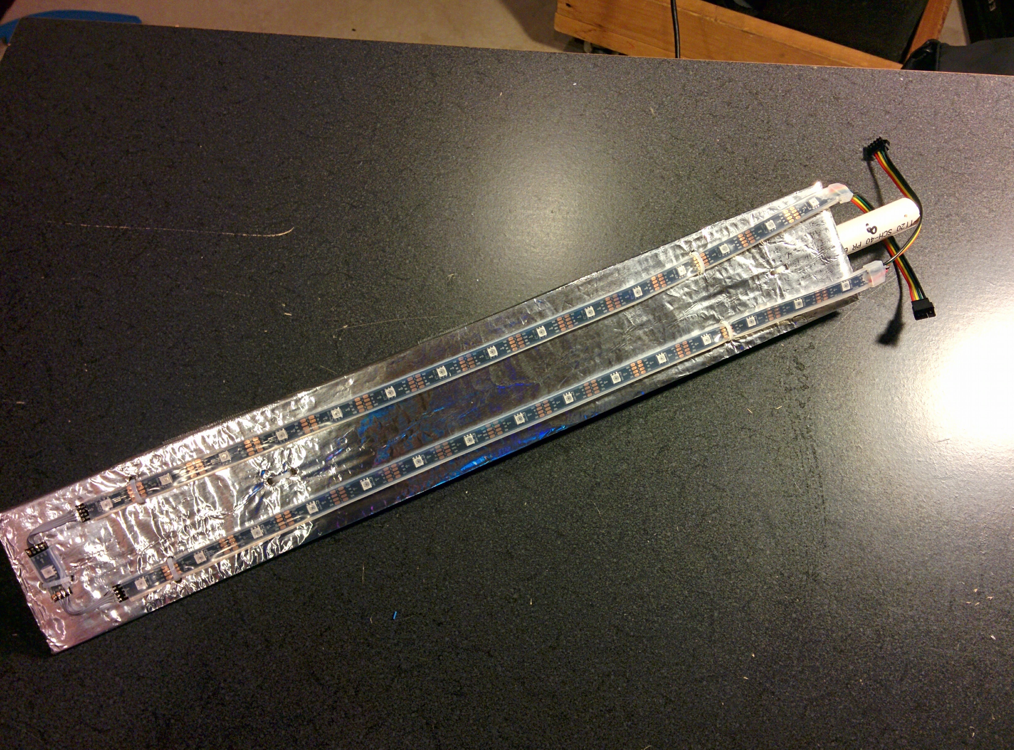
After getting the first board completed, I was able to reproduce the construction process and mass-produce the remaining seven panels.
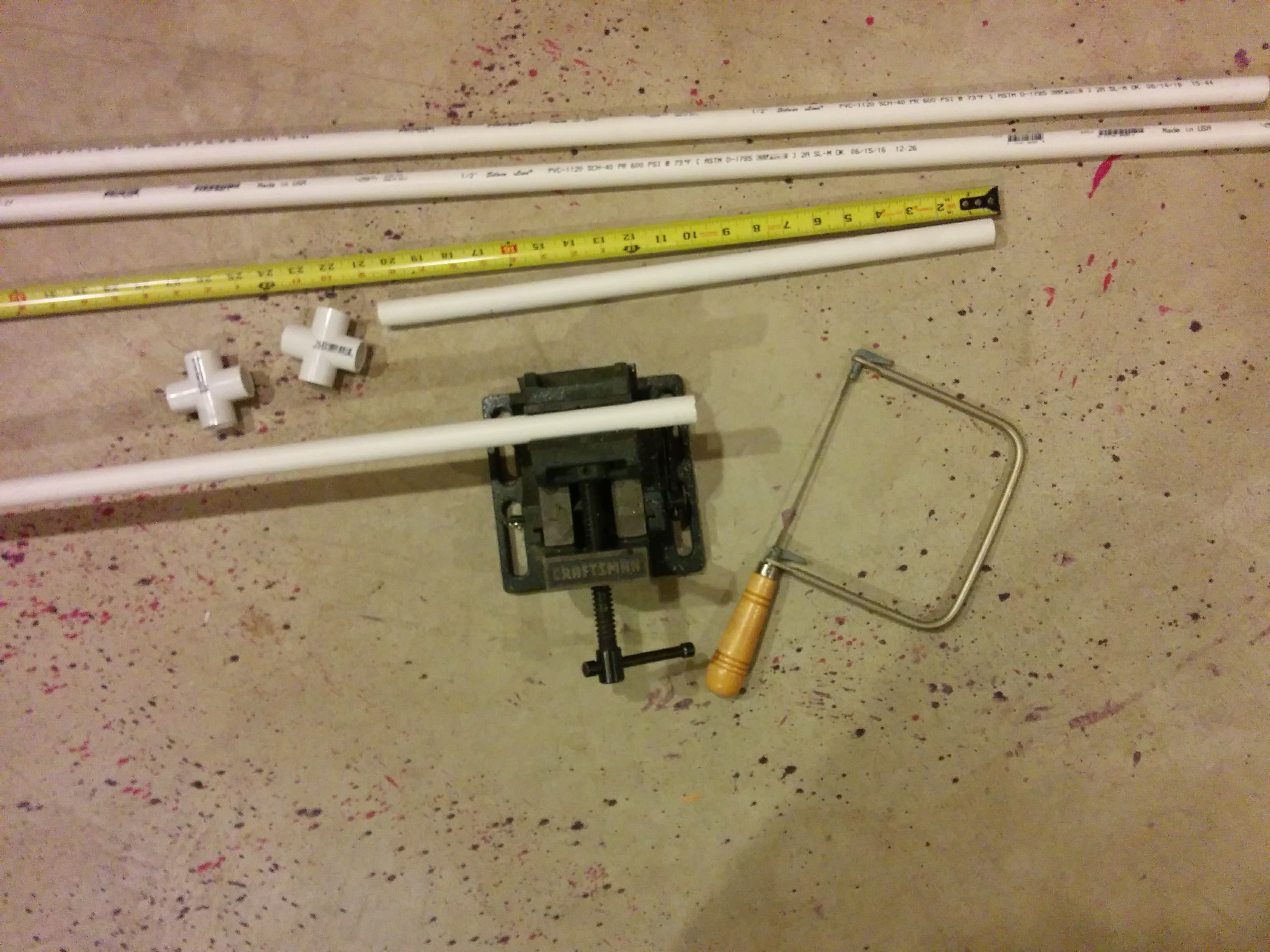
Another important consideration of this project was the skeleton that would support all of the panels. I made a trip to Lowe's hardware, and picked up a pair of 4-way PVC pipe connectors for the center hub, and a few lengths of pipe that would be used to support each of the panels:
After a bit of sawing and assembly, I was able to put the frame together…
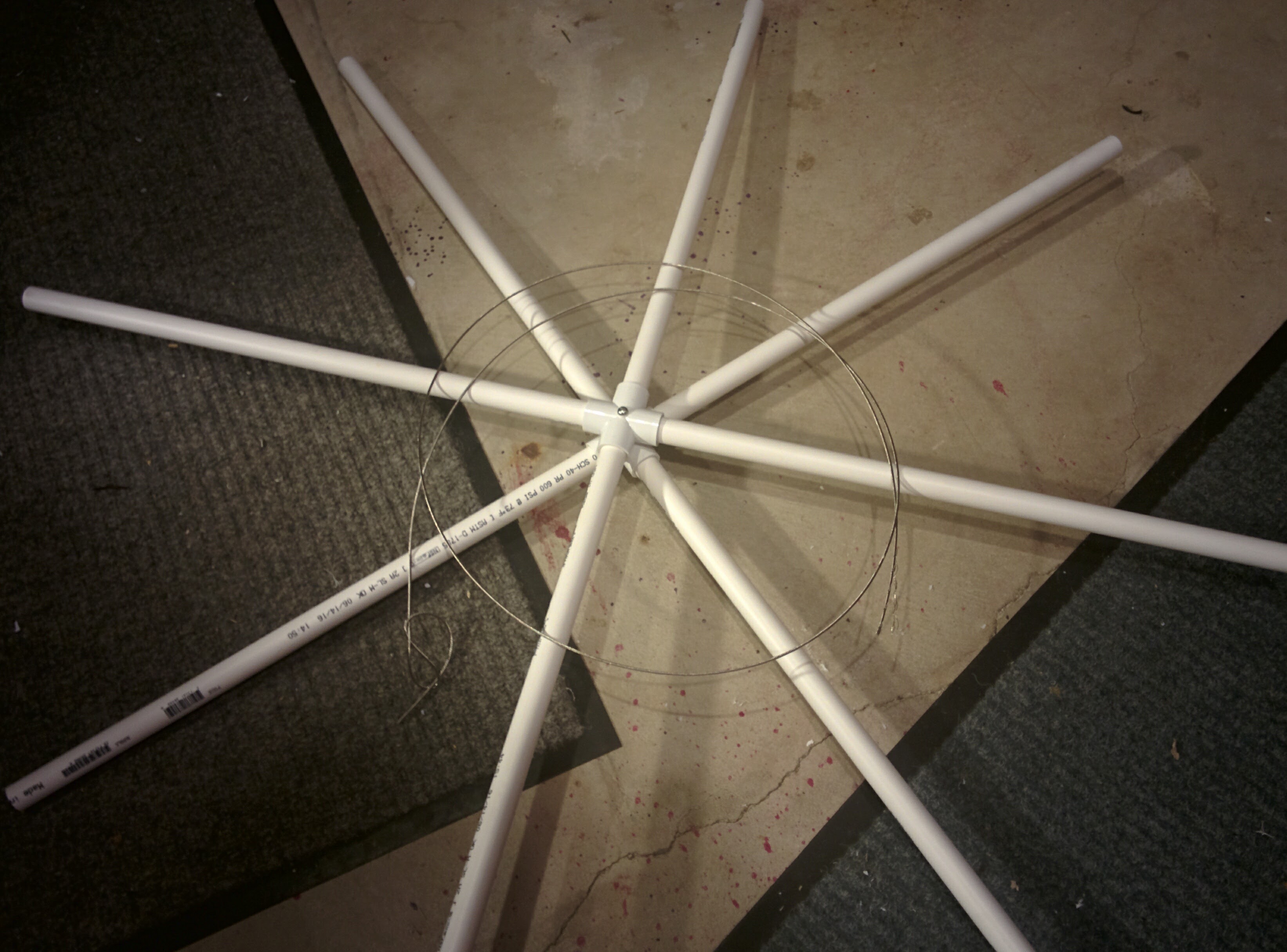
…and then started attaching the panels onto the frame.
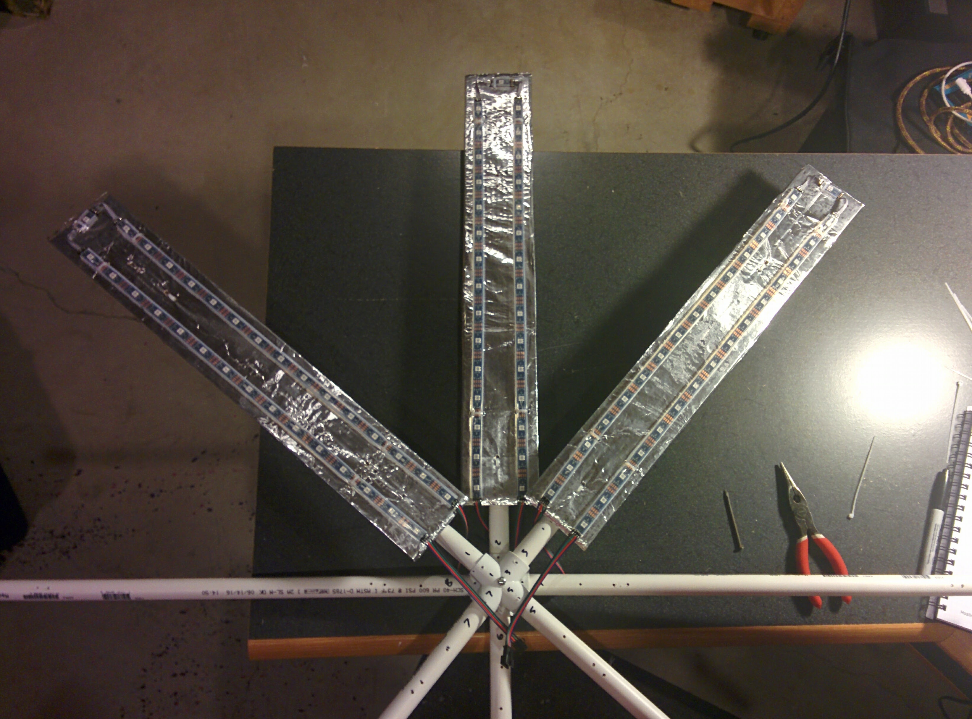
I wanted the finished project to be modular, so that the panels could be connected and disconnected easily. This added a bunch of additional work, since each panel needed two connectors soldered on (8 more solder-joints per panel, thus 64 more solder-joints overall):
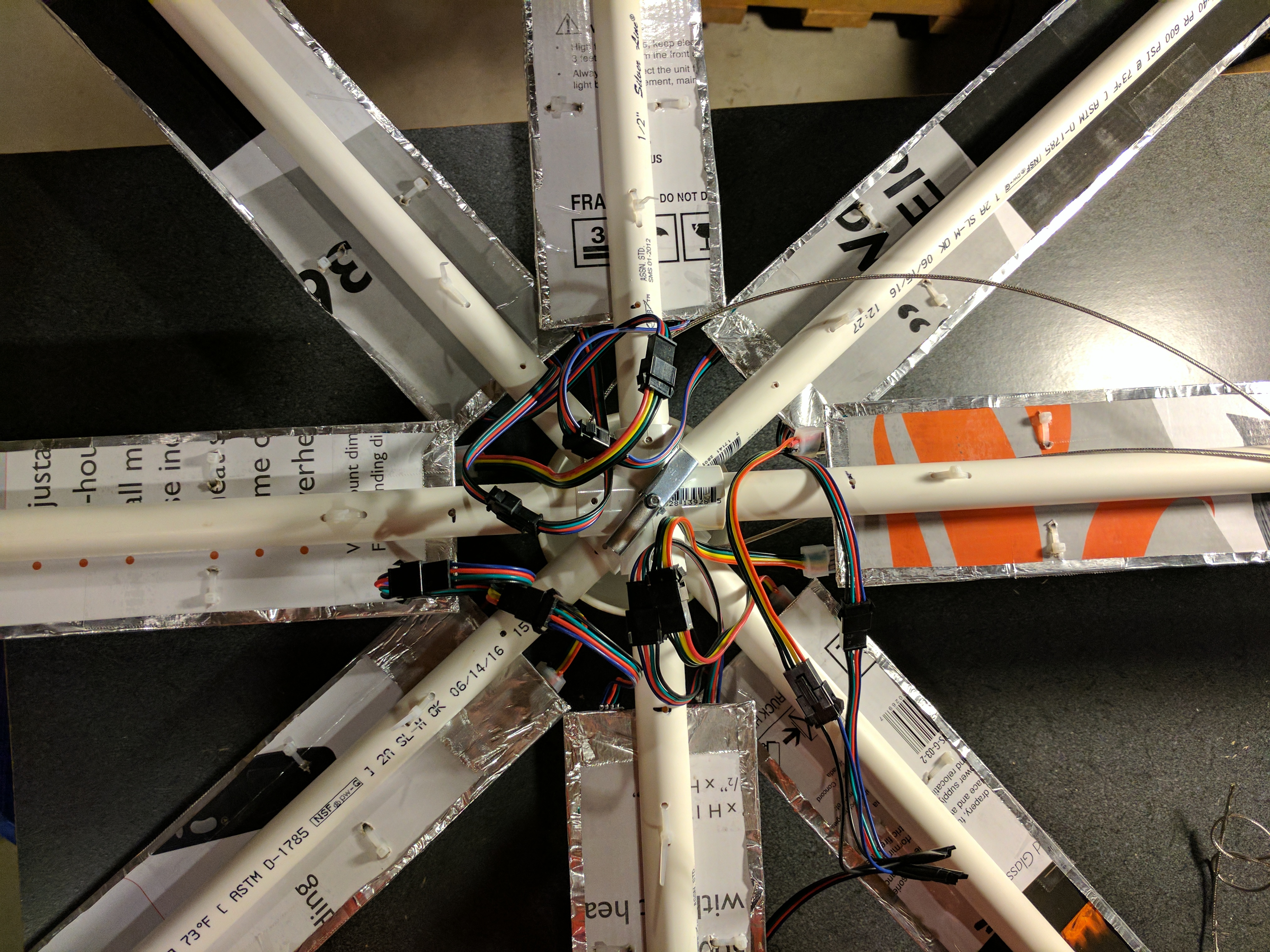
Eventually, the connectors and circuits on the breadboard were transferred and soldered to a proto-board.
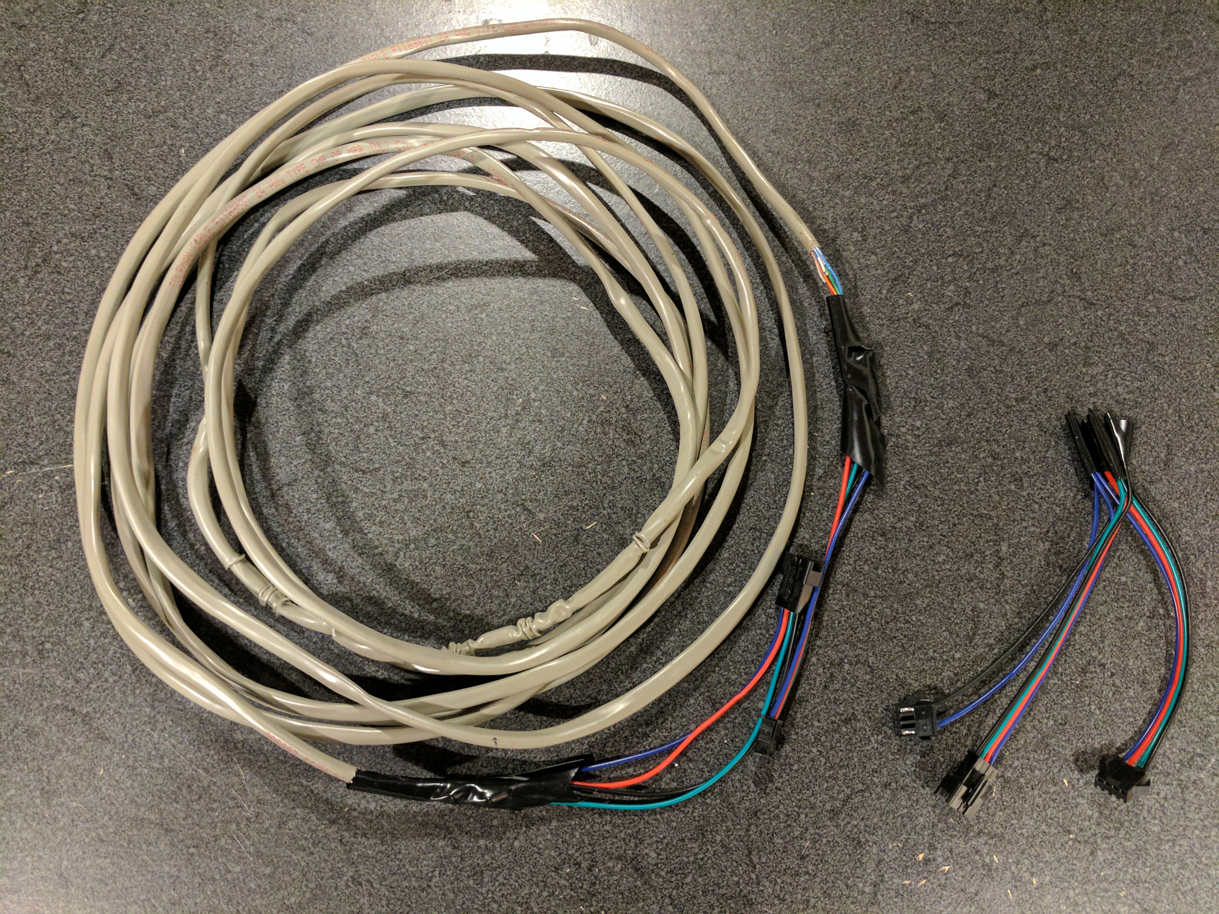
In order to allow for more distance between the LED display and the RasPi, I took some CAT-5 cable and turned it into an extension cord. Due to the power needs of the LEDs, I allocated two wires in the cable for +5 volts, and 2 more for the ground. I also discovered that having the LED strips connected in a very long series caused a noticeable voltage drop by the time power arrived at the last panel (it appeared dim compared to the first panel), so I built a "Y-connector" that would allow power to connect to both ends of the display.
Programming
After getting the whole thing built, it was time for the really fun part—writing code to bring things to life!
Since I wanted to have the logo controlled via the Internet, I had to figure out the best approach. Zapier's Storage Service was a great fit. It's like a lightweight JSON persistence database, where the data can be easily saved and retrieved using basic HTTP requests. Best of all, the data can also be easily updated using a Zap for a simple way to control the lights.
I then added a main NodeJS program running in the RasPi that just loops forever, and retrieves the current JSON from the Storage service (using a key specified in an environment variable). The program then calls the functions that were specified by the JSON data from Storage.
You can find the code on GitHub.
Simulating Things
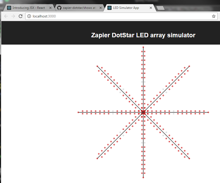
During the coding process, there were times when I was travelling and didn't have access to the display. Since everything is "just Javascript," I put together a simulator using ReactJS in the browser so that I could code, test, and tune the shows.
The major discrepancy was that computation intensive shows (like the rainbow effect) ran smoothly in the browser, but failed to run smoothly in the first generation RasPi I had connected to the display. Performing 248 HSB to RGB calculations 10 times a second was too much work for the RasPi to handle. Fortunately, Zapier co-founder Bryan Helmig came up with an implementation to cache the calculations, and then "shift" them across the display for a much smoother result.
Building the Front-end
Another facet of the programming is figuring out the front-end interface where you can select show styles and colors. This could have been something built in React, Angular, Ember, or a variety of libraries/frameworks, but the easiest approach was setting up a custom form on Formstack (since they support RESTHook triggers that provide nearly instantaneous data transfer).
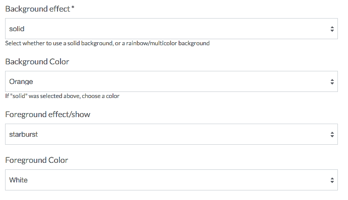
After creating the form, I setup a Zap that would receive the information, and then used a Javascript Code step to convert the colors and settings into a JSON object, which it would then write into the Zapier Storage service (using the same key the RasPi was using). You can find the actual code in this gist.
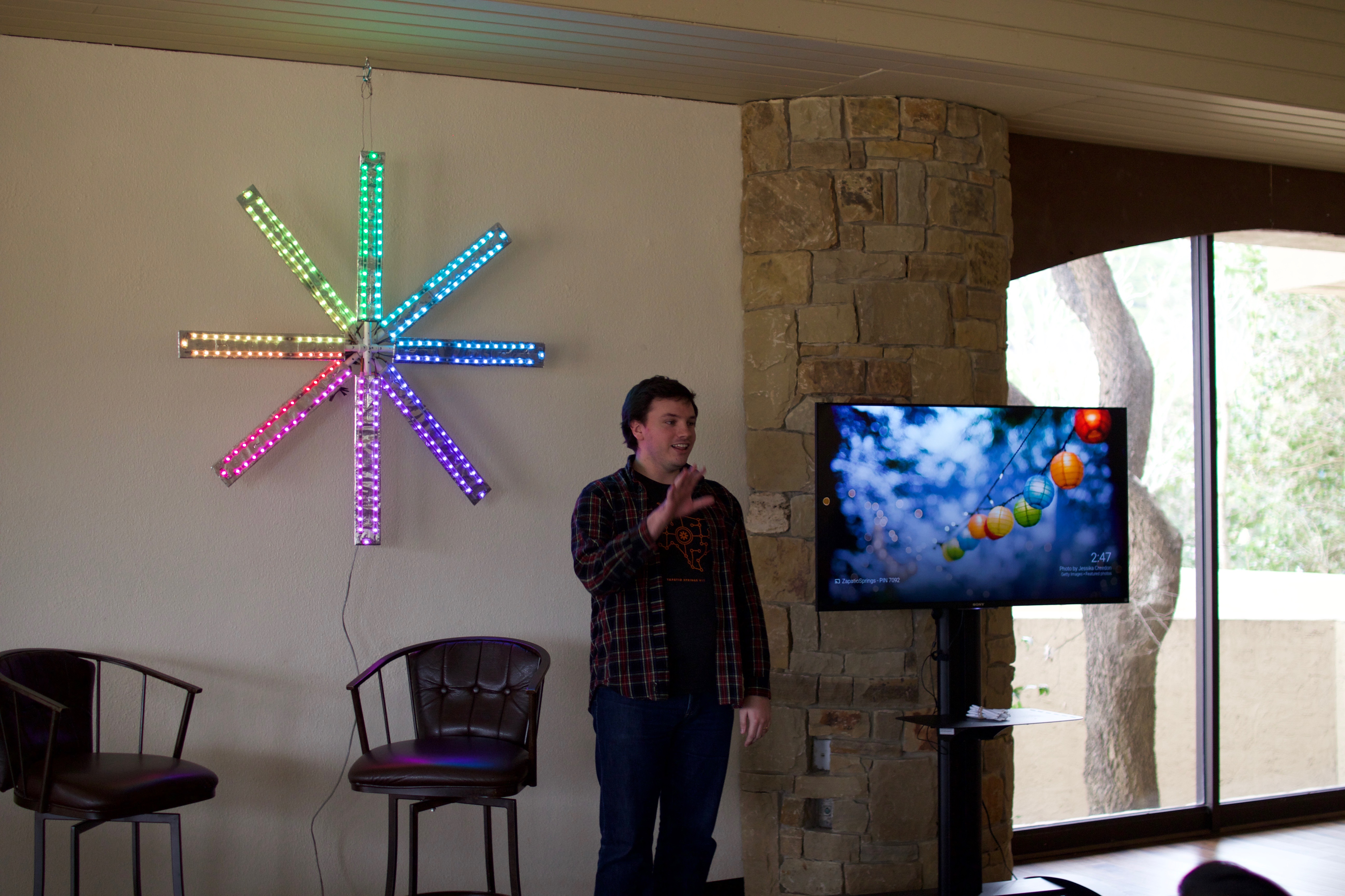
The Illuminated Zapier was a great addition to our 2017 Winter retreat at Tapatio Springs, Texas. The team loved changing the colors/patterns when people were presenting.
Your Next Project
If you're feeling inspired to build a project that connects something to the cloud, there are a bunch of great services available to handle parts of the work, and hardware that makes it simple to turn your idea into reality.
One of the easiest ways to get data flowing is with a Zap. If your project is a data logger (like a temperature or light sensor), setup a Zap using the Webhook trigger, and then have your project send data to the Zap's Webhook URL. From there, your Zap can write the data into a data-logging service like an Airtable database, Google Sheets or Excel Online spreadsheet, or your own database. You could even pass the data into an online graphing service like Dasheroo or Klipfolio, or get notifications about the data via Pushbullet or SMS.
Alternatively, if your project needs to receive commands from external sources, then the best approach is to use Zapier Storage for an intermediary JSON storage, so that your project can restart (and resume) with the same data if necessary. This also give you the capability to synchronize data between multiple instances of your project. And to send those commands, a form app is often the quickest and most flexible way to prototype and deploy your projects.
If you're still looking for thoughts or ideas about getting things connected with your project, we'd love to hear from you. Comment below or tweet @zapier—we'd love to hear about what you're building!
See It Live
If you made it this far, you can take control of the Illuminated Zapier, and if the live-stream is still running, you can see your settings in action!
Comments powered by Disqus